.png)
How to make a Smart Robot Car using an Arduino
- Aziel Habtemichael
- Dec 24, 2021
- 9 min read

In this project, we want to make a robot car that will drive using your phone. The goal is to build a drive train and use a Bluetooth module to connect it to our phone and drive it. The things we will be focusing on are how motors work with Arduino and using the Bluetooth sensor.
Materials
Arduino Mega
DC Motor (x2)
Motor Controller
Breadboard Small
9V Battery
Bluetooth Module
Jumper Wires
Robot Chassis (could be anything)
Phone
Software
Elegoo Ble Tool - Android and Iphone
Circuit
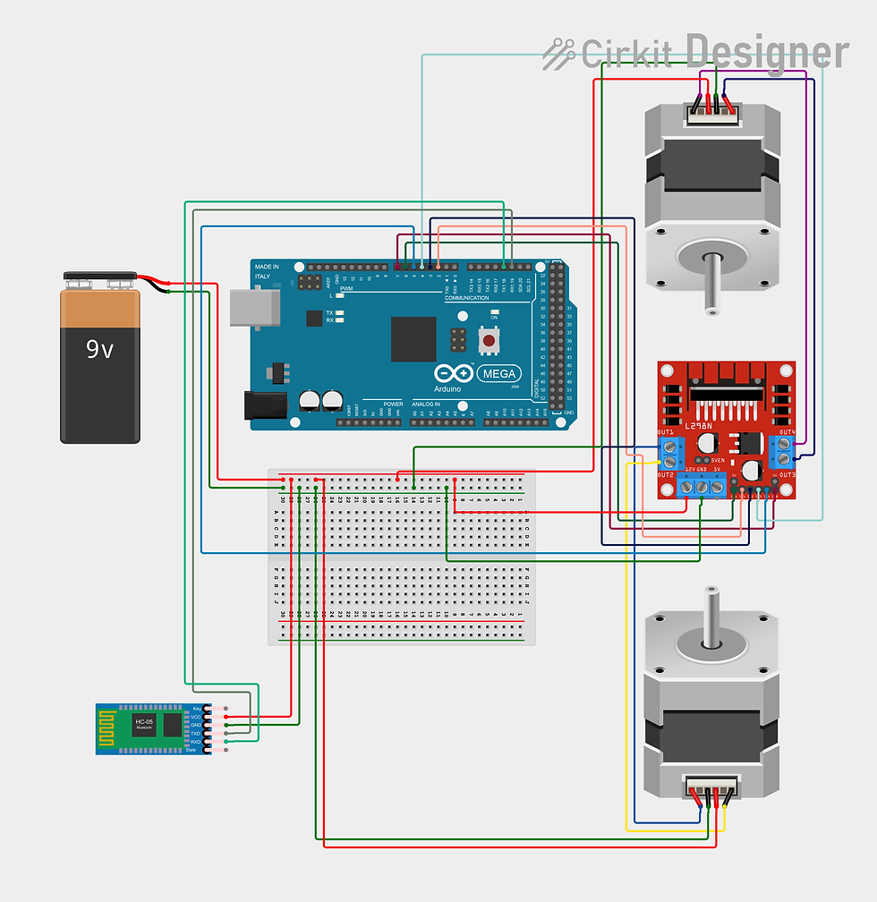
In this circuit, our goal is to distribute enough power to the motors through the motor controller and make sure we receive value from our Bluetooth Module. First, we're going to power our breadboard with at least a 9V Battery. Next, we're going to start by wiring the motors. We have two motors and a motor controller. So we want to connect the motors to the motor controller so that we want to control it. The L298N Motor Controller helps us control the two motors. Some motors have 6 wires, some have 4 and some have 2. It all comes down to what kind of motor you have. The basic 2 wired motor has only a positive and a negative which you can connect to the motor controller. We can connect the positive to OUT 1 on one side and OUT 3 on the other side. And we can connect the negative to OUT 2 on one side and OUT 4 on the other. The 4 wired motor and 6 wired motors have a built-in encoder that allows us to control the speed precisely. And for those, we just add the other two encoder wires go to our breadboard to the positive and negative. Now we will connect the motor controller to the breadboard's positive and negative to power it through the 12V and GND pins. Then we have to connect the motor controller to the Arduino to communicate with our motors. We're going to connect pins INT 1, INT 2, INT 3, INT 4 to pins 2, 3, 4, 5 respectively. INT 1 and INT 2 are for motor 1 and INT 3 and INT 4 are for motor 2. Finally the Bluetooth Module. This is what's going to help us connect the Arduino with our phone through Bluetooth. For the Bluetooth Module, we will connect the VCC and GND pins to our breadboard's positive and negative to give it some power. Then we are going to connect the TXD pin with the Arduino's RX1 pin and the RXD pin with the Arduino's TX1 pin.
Programming
First, we need to add the Arduino JSON library that allows us to communicate with our phones. To do that we have to go to the scroll-down menu at the top to sketch. Then we will find include library, then we're going to choose the first option, manage libraries. The library manager will pop up, and we're going to search up "ArduinoJson" and "ArduinoJson" should be as an option and we're going to install that. And that should have whatever we need for our Robot.
So we're going to start by including the library we've just installed. Now we're going to declare 6 variables. The first four are for our motors. Since we connected two pins per motor we have four variables. One pin in a motor is used for doing forward and the other is used for going backward. The other two are our speed variables for each motor. And all six variables are set to the pins we connected to the Arduino. And the last two variables are our speed values. The maximum speed/value the motors can take in is 255. So I set the regular car's speed to 150 and the high speed to 255. Feel free to change these values whenever you want. Lastly, we opened a new JSON document for us to communicate with our phones.
Now we're going to be making our functions. So let's look at the first one. To go forward we need both motors to go at the same speed. So for the first motor, we have two pins. One pin makes it go forward and the other makes it go backward. So to make it go forward we need to turn one on and the other off. To do that we set motor1pin1 to "HIGH", which means on, and we set motor1pin2 to "LOW", which means off. So this motor will go forward. And for the second motor, we set motor2pin1 to "LOW" and motor2pin2 to "HIGH". We reversed this because the motors are going to be opposite from each other. So both motors should be going in the same direction. It depends on how you set up your motors, so if they go backward you can always reverse them. For the ENA and ENB pins, we're using the "analogWrite" because we're setting the speed, whereas for the other pins we're just turning them on and off. And we set them equal to car speed which is equal to 150. So both motors will go the same speed and the same direction. And for the back function, we did the same thing but reversed everything which will make it go the opposite direction from where it was going. But we keep the speed the same for both motors. For turning left or right we want one motor to go one direction and the other to go the opposite way. So for the right turn, we want the right motor to go backward and the left motor to go forward. So we set motor1pin1 to "LOW" and we set motor1pin2 to "HIGH". This is going to go back and for the second motor, the left motor, we set motor2pin1 to "LOW" and we set motor2pin2 to "HIGH" which makes it go forward. This makes it turn right. And then we gave both motors the same speed. To turn left we want the left motor to go backward and the right motor to go forward. So we do the same thing but reverse everything and we also give both motors the same speed. When we're driving the robot, if we're not moving at all we want the motors to stop otherwise it going to keep on going forever. So we set up a stop motors function that turns off the motors. We simply just set all the motor pins to LOW. And we have an end route function that stops forever. If we want to drive it 0 which means the robot goes by itself, we want to use this function to stop at the end of our route. What this does is that it stops the motors forever.
Now let's move on to the setup. The setup is pretty straightforward. We are only setting up our serial monitors. We have two serial monitors. We need one serial monitor dedicated to the data we receive from our phone. And we want those to be on the same baud rate.
Now let's look at the loop. We started by receiving the data we get from the phone. We created a variable called msg that we're going to use the data we receive from the phone. So how the app work is that it sends messages when a button or the joystick is used. We're only going to be using the joystick do let's focus on that. When we use the joystick, it sends sets of information. We're only using the first two. The first one tells us the id of the button/joystick.
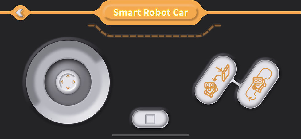
So if we drag the circle of the joystick upward, it will send the id 3. And the second set of information is used for our speed. If you dragged the circle of the joystick a little bit, the speed should be low but if you drag it to its maximum it should go full speed.
The first set of data, the id, is sent as "D1" in the document. And the second set of data, the speed, is sent as D2 in the document. The first thing we did, is set car speed to the D2 which is the speed we get from our phone. And we're serial printing the whole message for debugging reasons. And then we have 5 if-else statements. They mean that if the joystick is dragged up, which has the id 3, it will call the forward function we created earlier. And the rest of them have the same process with their ids. We're using else if statements for others because that means it will check all of them one after the other and if none of them are called, it will call the function stop motors which will do nothing. This means that as long as we use the joystick the robot won't move. If you want to drive this robot autonomously, get rid of all the if statements and simply call the functions with delays in between for how long you want it to go.
#include <ArduinoJson.h>

int motor1Pin1 = 2;
int motor1Pin2 = 3;
int motor2Pin1 = 4;
int motor2Pin2 = 5;

int ENA = 6;
int ENB = 7;

int carspeed = 150;
int highspeed = 255;

DynamicJsonDocument doc(1024);

void forward() {
  digitalWrite(motor1Pin1, HIGH);
  digitalWrite(motor1Pin2, LOW);
  digitalWrite(motor2Pin1, LOW);
  digitalWrite(motor2Pin2, HIGH);
  analogWrite(ENA, carspeed);
  analogWrite(ENB, carspeed);
  //delay(x);
}
void back() {

  digitalWrite(motor1Pin1, LOW);
  digitalWrite(motor1Pin2, HIGH);
  digitalWrite(motor2Pin1, HIGH);
  digitalWrite(motor2Pin2, LOW);
  analogWrite(ENA, carspeed);
  analogWrite(ENB, carspeed);
  //delay(x);
}
void right() {
  digitalWrite(motor1Pin1, LOW);
  digitalWrite(motor1Pin2, HIGH);
  digitalWrite(motor2Pin1, LOW);
  digitalWrite(motor2Pin2, HIGH);
  analogWrite(ENA, carspeed);
  analogWrite(ENB, carspeed);
  //delay(x);
}
void left() {
  digitalWrite(motor1Pin1, HIGH);
  digitalWrite(motor1Pin2, LOW);
  digitalWrite(motor2Pin1, HIGH);
  digitalWrite(motor2Pin2, LOW);
  analogWrite(ENA, carspeed);
  analogWrite(ENB, carspeed);
  //delay(x);
}
void stopMotors() {
  digitalWrite(motor1Pin1, LOW);
  digitalWrite(motor1Pin2, LOW);
  digitalWrite(motor2Pin1, LOW);
  digitalWrite(motor2Pin2, LOW);
}

void endRoute() {
  while (1) {
    digitalWrite(motor1Pin1, LOW);
    digitalWrite(motor1Pin2, LOW);
    digitalWrite(motor2Pin1, LOW);
    digitalWrite(motor2Pin2, LOW);
  }
}


void setup() {
  // put your setup code here, to run once:
  Serial1.begin(9600);
  Serial.begin(9600);

}
void loop() {

  if(Serial1.available()){
    String msg = Serial1.readStringUntil('}') +('}');

    if(deserializeJson(doc, msg)){
      Serial.println("deserializeJson() failed");
      return;
    }

    carspeed = ((int) doc["D2"]);

    Serial.println(carspeed);
    Serial.println("msg: " + msg);


    if(doc["D1"] == 3){
      Serial.println("forward");
      forward();
    }
    else if(doc["D1"] == 2){
      Serial.println("right");
      right();
    }
    else if(doc["D1"] == 4){
      Serial.println("back");
      back();
    }
    else if(doc["D1"] == 1){
      Serial.println("left");
      left();
    }
    else {
      Serial.println("stop");
      stopmotors();
    }

  }

}
After finishing writing the code, download it using the USB cable to the Arduino. Before that, you have to make sure the board type is the right one and it's set up to the right port. To do that go to the tools section choose the board type and port. In this case, we are using an Arduino Mega. We need more battery so you would have to unplug the USB cable and connect it with a battery. We can only test it our we build the robot.
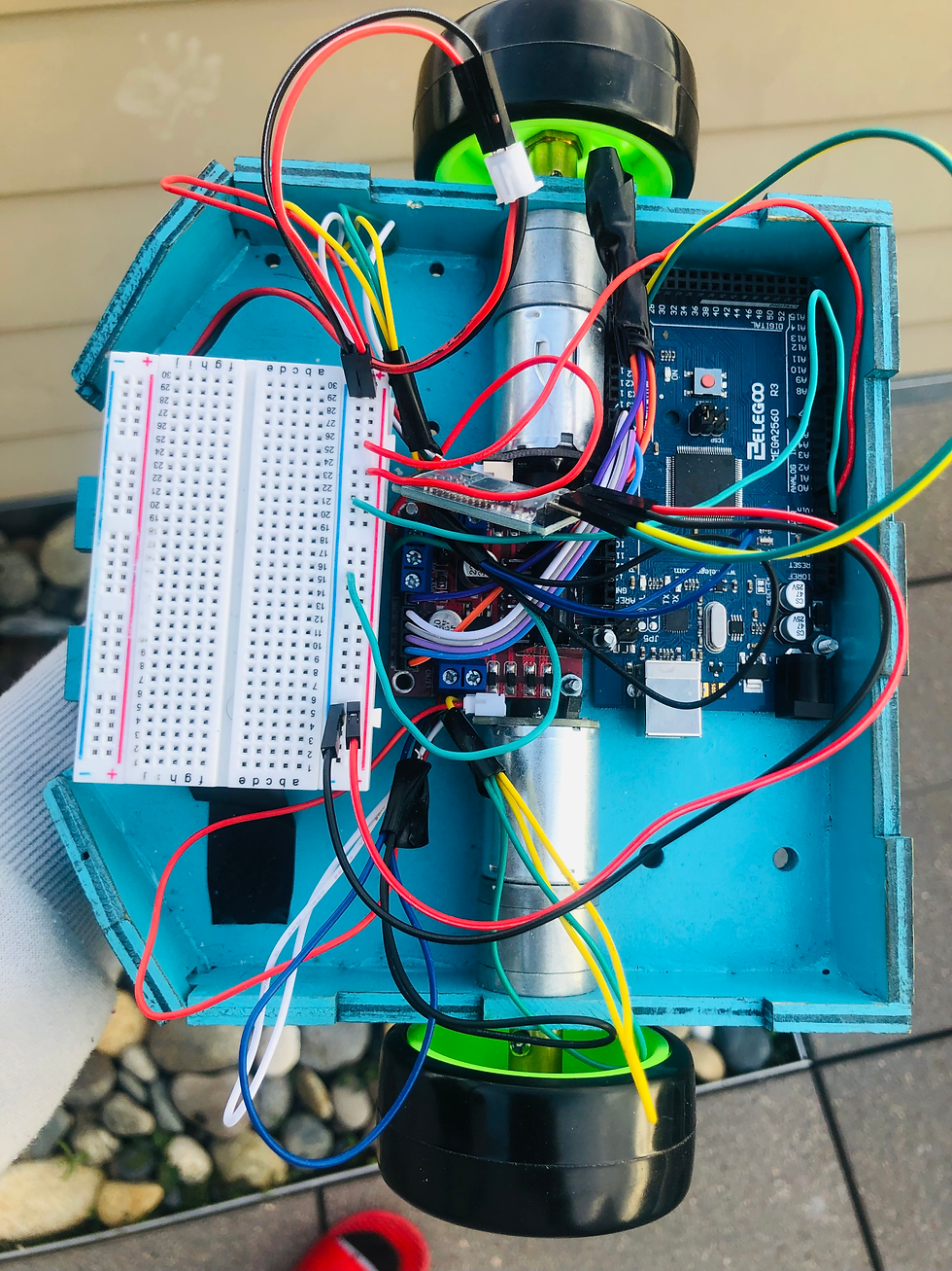
Building
So the most important thing about the building is that we are building a robot with two wheels and two motors. We need to set up the motors in a way that they face each other. W need to make sure our Arduino board, motor controller, a small breadboard, and our battery all fit there. The best way to put them all in there is to bring the nuts and bolts to mount them on whatever material we decide to use. We need to find any chassis for the robot. If you have a 3D printer, this would be a great time to practice your CAD design skills. For the people that don't have a 3D printer, we have to be creative. In this example, we used a wood that worked perfectly and we did some editing. We drilled the holes for the motor and we drilled some holes for the nuts and bolts to mount them into the wood. In this robot, it's all squashed into one because we managed to use this small chassis with big parts. You might have some troubles with mounting the motor and attaching it to the wheel because its shaft is weird. Most of the work done with building depends on you because we all have different things in our house so our robots will look different.
Finally, connect the battery to the robot and it should turn on. The Bluetooth receiver should be blinking. If it's blinking it means it's looking for a connection and we're ready to go. So we're going to open the Elegoo Ble Tool app. When we open it we should see a smart robot car as the first option and we're going to open it. And then we're going to click Rocker Control. That should put us in the place where we can drive our robot, but we have to connect it first. It should say "Connect your device now?" and click ok. After that, we should click on the three-dot menu on the top left corner of the screen. And then it should display a bunch of Bluetooth devices. And an ID of "MLT-BT" with some number after it should show up. And we're going to click that. After that, we should be connected and ready to go. You can now drive your robot. For any debugging purposes, connect your robot to the computer and open up the serial monitor in the Arduino and as you move around the joystick you should see messages there.
Make sure to like the post
Comment down below if it worked for you, any problems you're running into, and what other projects you want me to keep doing!

Comments