.png)
How to move two Servo motors with a Joystick
- Aziel Habtemichael
- Jan 30, 2022
- 3 min read

In this project, we want to turn the servo motors to turn using our joystick. We are going to focus on how the joystick module works. And we're going to turn the servos using it.
Materials
Arduino UNO
Joystick Module
Servo (x2)
9V Battery
Jumper wires
If you don't have any of these components, you can buy the kit in our shop:
Software
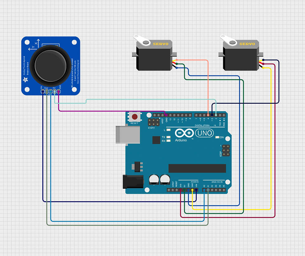
Circuit
In this circuit, our goal is to give enough voltage to our electrical components so that we can get position values from the joystick and turn the servo. First, we're going to attach a 9V battery through the jack next to the USB port. Next, we're going to focus on the joystick module. We have 4 pins to connect to the Arduino, the other one is optional. We have a 5V/VCC that connects to our Vin pin, which is our positive and our GND pin connects to our GND pin in the Arduino. Then we're going to connect VRx, which is the x-axis, to A1 and connect the VRy, which is the y-axis, to A0 in the Arduino. The SW pin is optional for this project. It reads when the joystick is pressed or not, which does not matter in this project. The Servos have three pins. The brown wires are going to be connected to the GND pin, the red positive wire goes to the 3.3V pin, and the VIN pin will give voltage to our Servos. And the yellow wires are our output wires, which are going to be connected to pins 3 and 4. So we have wired the whole circuit. A good thing we accomplished is that we didn't need any type of breadboard.
Programming
Now let's build our code. We started by including our Servo Library. Then we created 3 PIN variables for our joystick. They are supposed to be the same pins we connected them in our Arduino. The next 5 variables are going to help us navigate our joystick and make it relative to our servos. Then we're creating two servo objects for our two servos.
Our setup is pretty simple. We have VRx and VRy, the x and y positions of our joystick, set to inputs because they're going to give us position values. And our SW_State is our state when our joystick button is clicked so it's an input. And for our servos, we attached them to 3 and 4, which are the exact pins we connected them in the circuit.
Now let's focus on the loop. First, we are setting our xPosition variable to the exact xPosition of our joystick by using the analogRead() function. It reads the values of the joystick. We do the same thing for the y position and set it to our yPosition variable. And we also do analogRead() for the joystick button to see if it's created or not. Then we're going to set our mapX variable to the map the xPosition from 0 to 180. Servo motors go from position 0 to 180. So we made the maximum value of the joystick 180 so it doesn't force the servos to go over the maximum position they can. We do the same thing for the y position by using the yPosition variable. Then we print our x value and set our first servo position to the new x value of the joystick, which is mapX. For the second servo, we print the y value and set the position to the new y value, which is mapY.
#include<Servo.h>

int VRy = A0;
int VRx = A1;
int SW = 2;

int xPosition = 0;
int yPosition = 0;
int SW_State = 0;
int mapX = 0;
int mapY = 0;

Servo servo1;
Servo servo2;

void setup() {
  // put your setup code here, to run once:
  Serial.begin(9600);

  pinMode(VRy, INPUT);
  pinMode(VRx, INPUT);
  pinMode(SW_State, INPUT);

  servo1.attach(3);
  servo2.attach(4);
}

void loop() {
  // put your main code here, to run repeatedly:

  xPosition = analogRead(VRx);
  yPosition = analogRead(VRy);
  SW_State = analogRead(SW);
  mapX = map(xPosition, 0, 1023, 0, 180);
  mapY = map(yPosition, 0, 1023, 0, 180);

  Serial.println("X position: ");
  Serial.println(mapX);
  servo2.write(mapX);
  Serial.println("Y position: ");
  Serial.println(mapY);
  servo1.write(mapY);

}
You have to make sure the board type is the right one and it's set up to the right port. To do that go to the tools section choose the board type and port. In this case, we are using an Arduino UNO. Download the code using the USB cable to the Arduino and see what happens.
Make sure to like the post
Comment down below if it worked for you, any problems you're running into, and what other projects you want me to keep doing!


Comments